hours left for
same day shipping

FEATURED ARTICLE
Published: 11/15/2022
When your clients’ outdoor lights aren’t working at their maximum potential—or they’re not showing up to work at all—a digital voltmeter can be a useful tool as it can calculate if fixtures are receiving adequate voltage. Let’s learn how to use a digital voltmeter to locate voltage drops in a low-voltage landscape lighting system.
Testing the voltage of a transformer, electrical sockets, and fixtures to locate a drop in voltage, voltmeters are helpful in both low voltage and line voltage outdoor lighting. The sockets and outlets are tested by interacting with the two probes attached to the voltmeter. Before we get into learning how to use the voltmeter, let’s examine the metrics a voltmeter uses.
Since the power for a landscape lighting system starts at the electrical outlet before navigating downward to the transformer, timer, photocell, connection terminals, wire hubs, and fixtures, you’ll want to test each component in that order to nail down the voltage drop.
First, set the digital voltmeter’s settings to Ṽ (AC) and the voltage to 200 V. Next, insert the probes into the outdoor electrical outlets’ sockets. The voltmeter’s reading should straddle somewhere between 118 and 125.
Keeping the voltmeter’s settings on Ṽ (AC) and 200 V, remove the timer and place the probes into its reciprocals. You should receive a similar reading as the outlet testing. Before continuing to the next step, place the timer or timer plug back into its receptacles.
Using the same settings as earlier, we’re going to test the photocell’s plug. Plug the voltmeter’s probes into the top two contacts. If the voltage is consistent, you’re ready to test the photocell. Testing the photocell is imperative since the power sails through it before reaching the wire hubs and lighting fixtures.
When testing the connection terminals inside the transformer, set the voltmeter’s settings on Ṽ and the dial on 20 V. Next, place one prong into the COM tap and the other into the first 12 V then test. The voltmeter should display 11 to 12 V. Perform this test on 14 and 15 V taps.
Following the supply line from the transformer down, check each wire hub’s internal connections from the different lighting fixtures. Verify the copper ends have a stable connection to the wire hub. You will also want to repeat this to check the voltage on each light.
Once you’ve discovered the voltage drop location, replace the light fixture's bulb with a working one. If the fixture emits little to no light with the new bulb, go ahead and check the wire connections.
Check if the supply wire to that fixture presents a smooth, secure connection. If the thread’s copper ends are dull and frayed, you may have to cut back the wire to have a solid copper end. Having the consideration of possibly splicing in more cable, use the new copper ends to form a connection.
If you’re still unable to spot voltage drops after exhausting the previous steps, you will need to assess any wire connection points beneath the ground.
You’ve successfully mastered how to use a digital voltmeter. If you have any questions about this handy tool or about any Lighting Warehouse products, contact our more-than-capable Customer Service team to set you on the right course.
Monday - Friday

Speak to us at 855-444-8424
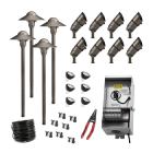 Easy-Install Kits
 Uplights
 Path & Walkway Lights
 Flood & Wall Wash Lights
 Hardscape Lights
 Step Lights
 Outdoor Deck Lights
 Outdoor Bulbs
 RGBW Color Lights
 Downlights
 Underwater Lights
 Bistro String Lights
 Holiday Decorations
 In-Ground Well Lights
 Accessories
 Solar Lights & Portables
 Specialty Lights
 Bollard Lights
 Tape Lights
 120V Landscape Lighting
 Dark Sky Approved Lights
 Connectors
 Wire & Cable
 Timers & Control Devices